
Clarifying the code
In the last post, we looked at the first part of the ‘Damage infliction’ method/subroutine. This name is one that I made up to make clear for myself what the method is for. Nowhere in the ‘disassembled’ code are these names to be found. And as you have probable noticed if you have debugged yourself, it is very easy to get lost in the code. Therefore, it is advisable to make notes about the code you have investigated. The disassembled code can be saved from the menu of the debugger (File -> Save disassembly) and then opened in a text editor. I have investigated the whole subroutine and here is the disassembled code with my notes.
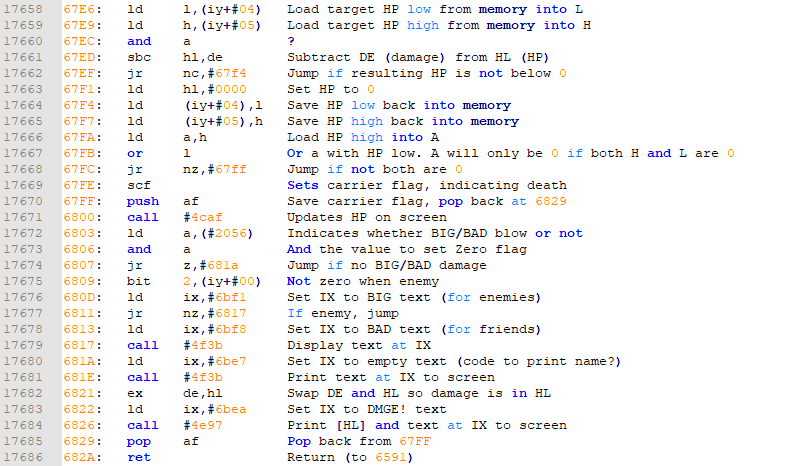
The first part, up until #67F7, we have discussed and are to calculate the new HP and correct if it is below 0. Now let’s talk about the rest of the method. I hope you know how binary numbers work, since we will be needing that to understand some of the used expressions.
The binary system
In short, each address is a value between 0 and 255 decimal, or 0 and #FF hexadecimal. In binary, these values are 0 and 11111111.
In our normal decimal system, the rightmost digit indicates the single numbers, the second digit the 10’s, then the 100’s, etc. In binary, the leftmost digit (which is called a ‘bit’) indicates the single numbers as well. But since possible values are only 0 and 1, the second bit indicates the number of 2’s. The third bit indicates the 4’s, then 8’s etc. And since the possible values of each bit are only 0 and 1, there can never be 2 of any bit. So there are never 2 4’s, but this would be one 8.
4 binary digits range from 0000 to 1111. 0000 is 0 in decimal. 1111 is 8+4+2+1 = 15 in decimal. This means there are 16 possible values. This is why these 4 bits are equivalent to 1 hex digit. A hex digit can range from 0 to F and also has 16 possible values.
| Decimal | Binary | Hexadecimal |
| 0 | 0000 | 0 |
| 1 | 0001 | 1 |
| 2 | 0010 | 2 |
| 3 | 0011 | 3 |
| 4 | 0100 | 4 |
| 5 | 0101 | 5 |
| 6 | 0110 | 6 |
| 7 | 0111 | 7 |
| 8 | 1000 | 8 |
| 9 | 1001 | 9 |
| 10 | 1010 | A |
| 11 | 1011 | B |
| 12 | 1100 | C |
| 13 | 1101 | D |
| 14 | 1110 | E |
| 15 | 1111 | F |
Now if you have a look online at the instructions that are available for arithmetic operations in the Z80, you will notice there are not a lot of options that you will recognize from normal math. We can add and subtract, but that is about it. There are some logical binary operations (called ‘bitwise operations’) that we can perform, however, and one of them we see in #67FB. To understand this, we need to think in binary, however.
In #67FA, the high part of the new HP is loaded into the A register. Since this is a number between 0 and 255 decimal (or 2 digits in hexadecimal), this number in binary can be represented as a 8 digit binary number. Then in #67FB, the value in the A register are being OR’d with the low part of the new HP. The OR is a bitwise operation which always operates on the A register and another number. It looks at each bit of both numbers (so first compares the first bit of both numbers, then the second etc) and results in a 1 if at least one of the both bits has a 1. So only if both are 0, the result will be 0. The resulting set of 8 bits represent a new number which will be loaded in to register A.
#67FC is then a conditional jump that jumps only if the contents of the A register is not 0. We know that the contents of the A register is the result of the OR, which is only 0 if both the high part and the low part of the HP were 0. So only if the HP as a whole is 0.
So only if the HP is zero, the statement at #67FE will be executed. The only thing this does is setting the Carrier flag. This is the same carrier flag we saw used to determine whether the resulting value was below 0. Here it is being set to determine whether the hit character has died. I found this out by experimenting and setting the flag manually by clicking it in the top of the CPU registers window.
The stack
The statement at #67FF push af is used to push the value of the AF register onto the STACK. This stack is the only window we haven’t used yet in the debugger. It is just a pile of values, globally available, on which you can PUSH values. Each new value will become the new top of the stack. Values can then be POP-ped back of the stack one at the time. And only the top of the stack can be POP-ped. So it is a last in-first out list.
At #6829 pop af, we POP the value back into the AF register from the stack. Why did we need to save the AF register value at #67FF? That is because the F part of that register is the state of all the flags. And because we have the Carrier flag indicating whether the target died, we need that restored into the carrier flag before we return to the calling code. Some logic to display hit and damage text has happened since, and so this flag has been reset a lot of times before we get here.
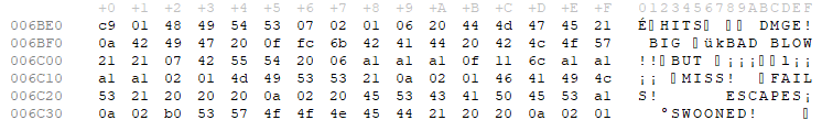
The remainder of the method is code to put the battle texts on the screen. First, one byte in memory, at address #2056 apparently indicates whether the hit is a big/bad blow or not. Some previous code where the damage was calculated apparently took care of this. Then for each text to display, the location of the text in memory is put into the IX register. If you would look at those addresses, you would see these texts indeed.
One of the methods to display text apparently uses the HL register to show the damage being done. That register holds the HP, however. That is why the DE and HL values are being swapped just before the call to display.
In the next post, we will greatly simplify this damage infliction method to make ourselves invincible. If there only was a way to determine whether we are running the code because we are hitting an enemy or we are being hit. Well, there is! Inside the damage infliction method, in the part where the various texts are being displayed, there is a statement which determines whether an enemy or a player is being hit. This is needed because that determines whether the blow is BAD or BIG. Lookup the expression and figure out how this works. We will use it in the next post.
Geef een reactie